|
|
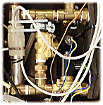
Cool plate - plumbing |
The circulation system is sealed and pressurised to about 150 kPa (1.5 bar). The pump sends the water stream first through the heater. After this it is routed directly to the cool plate. If cooling is required the water is routed through the heat exchanger, whose other circuit is from the cooler, which is always active (though it may be manually disabled if the coolplate will always be above ambient for the experiment).
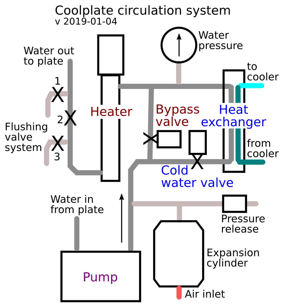
Schematic diagram of the water circulation system.
The heater is always in the circulation path. When cooling is required the heater is switched off and the cold water valve is opened, then the bypass valve is closed. There is never a time when the heating is working against the cooling. The apparatus is either heating, circulating through the bypass valve with the heater off, or circulating through the cooling valve. This is unlike most temperature control systems which have continuous cooling counteracted by heating to the required temperature.
The reason for this is that compression cooling units do not like being switched frequently because the motor then starts against a high fluid pressure. That is why the cooling is provided indirectly through a heat exchanger.
The pump is Grundfos up15-14b pm 80mm-1/2.
The data sheet is at:
https://product-selection.grundfos.com/product-detail.product-detail.html?custid=GMA&productnumber=96433883&qcid=465518914
This is the smallest commonly available standard commercial pump. It was selected as it is a high quality pump, which is intended for continual use over several years, and is energy efficient. It is intended for maintaining a small circulation of hot water in a house. Energy efficiency is prioritised over pressure or head; the pump is only capable of maintaining the flow if there are no kinks, air bubbles or other hindrances.
The heat exchanger is rated at 3kW. It is a brazed, counterflow sheet metal type, the smallest commonly available, intended for small scale heating uses. It has four 3/4” connections, which must be reduced to 1/2” with fittings to fit the rest of the pipework. The dimensions are 195 x 83 x 30mm but it will take up more space because it must be carefully insulated because it is always the coldest place in the entire apparatus.
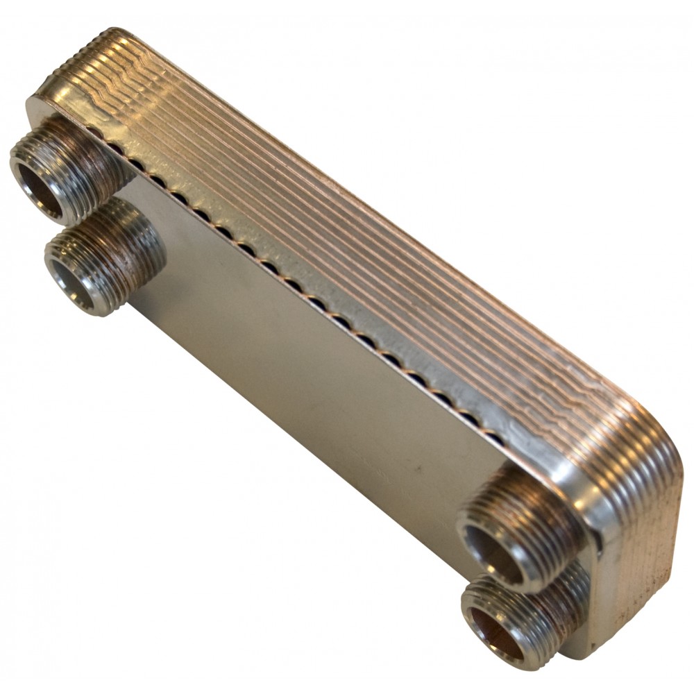
The high transfer wattage is necessary because, unlike the heater, there will often be only a small temperature difference between the cold water from the cooling device and the required temperature for the plate cooling circuit.
The heater is model AHPF-082:
https://www.omega.com/pptst/AHPF_HEATER.html
240V 600W, stainless steel construction.
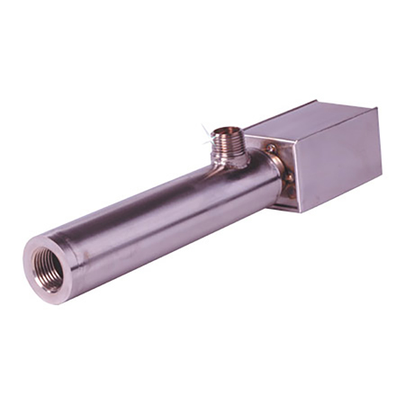
The heater should be lightly insulated, with two temperature sensors tucked between the insulation and the barrel. The heater will overheat if the water circulation is stopped, by a kink in the tubing for example. The computer measures both temperatures and closes down the cool plate entirely if over-heating is detected. As a final defence against overheating there is a fusible link which breaks the power supply to the rpi.
The brass solenoid valves are nominally rated at 12 V, 3 A. https://www.adafruit.com/product/996. However, the water pressure exerted by the pump is very small so the valves only need 6 V at 1.6 A to function reliably.
The expansion vessel is a Reflex Refix DE 2 10 bar 2 Litre.
It has a diameter of 132 mm x 260 mm high, which is the smallest generally available. It is needed to maintain a constant pressure in a circulation system with a constantly varying temperature. The pressure on the air side of the rubber membrane is set to 50 kPa through the standard automotive valve.
The external water chiller is a typical industrial cooler, from Guangzho Teyu Electromechanical Co Ltd. http://images10.newegg.com/UploadFilesForNewegg/itemintelligence/Callaway%20Golf/CW_5000_hiendro1445108848123.pdf
The chiller uses about 500 W while the compressor is running. The refrigeration capacity for a 10 °C temperature difference across the heat exchanger is about 1.4 kW. However, in practice the temperature difference will sometimes be quite small, around 3 °C so one can expect about 500 W cooling power. For most purposes this will be entirely adequate. It is important not to install a high capacity cooler because this is the biggest heat source in the entire apparatus. In a small room it will cause instability in the room temperature control as the device switches between full power and no power, in a cycle that depends on the load imposed by the cool plate temperature cycle.
The chiller has a manual on/off switch, and manual setting of the minimum temperature. These have to be set at the beginning of the experimental run. The power to the chiller is, however, routed through a relay so that the rpi can switch it on and off under program control.
There are three manually operated valves shown on the diagram above. These are for flushing air from the system. A simple bleed valve as used on domestic radiators will not work, because the top of the system cannot be defined exactly. It is necessary forcibly to flush water through the pipe work to remove all the air. This is done by first closing the valve 2, which is open in normal operation. Then water is injected through valve 1, and allowed to escape through valve 3. When the water streams clear of bubbles, valve 3 is closed while water is still injected through valve 1 until the pressure gauge shows about 50 kPa (0.5 bar over ambient) pressure. Then valve 1 is closed and valve 2 is opened to allow normal recirculation through the now sealed system.
The water pressure is quite low, because of the vulnerability of the flexible hose and the clamps. The flushing and pressurising is best done with a garden spray with about 5 l capacity and typically able to attain about 200 kPa pressure.
The circulating water should be about half and half tap water and distilled or deionised water. This minimises corrosion and deposition of minerals.
Next page: the control logic